BBMPulser Electronic Circuits
Open Source Magnetic Pulsers
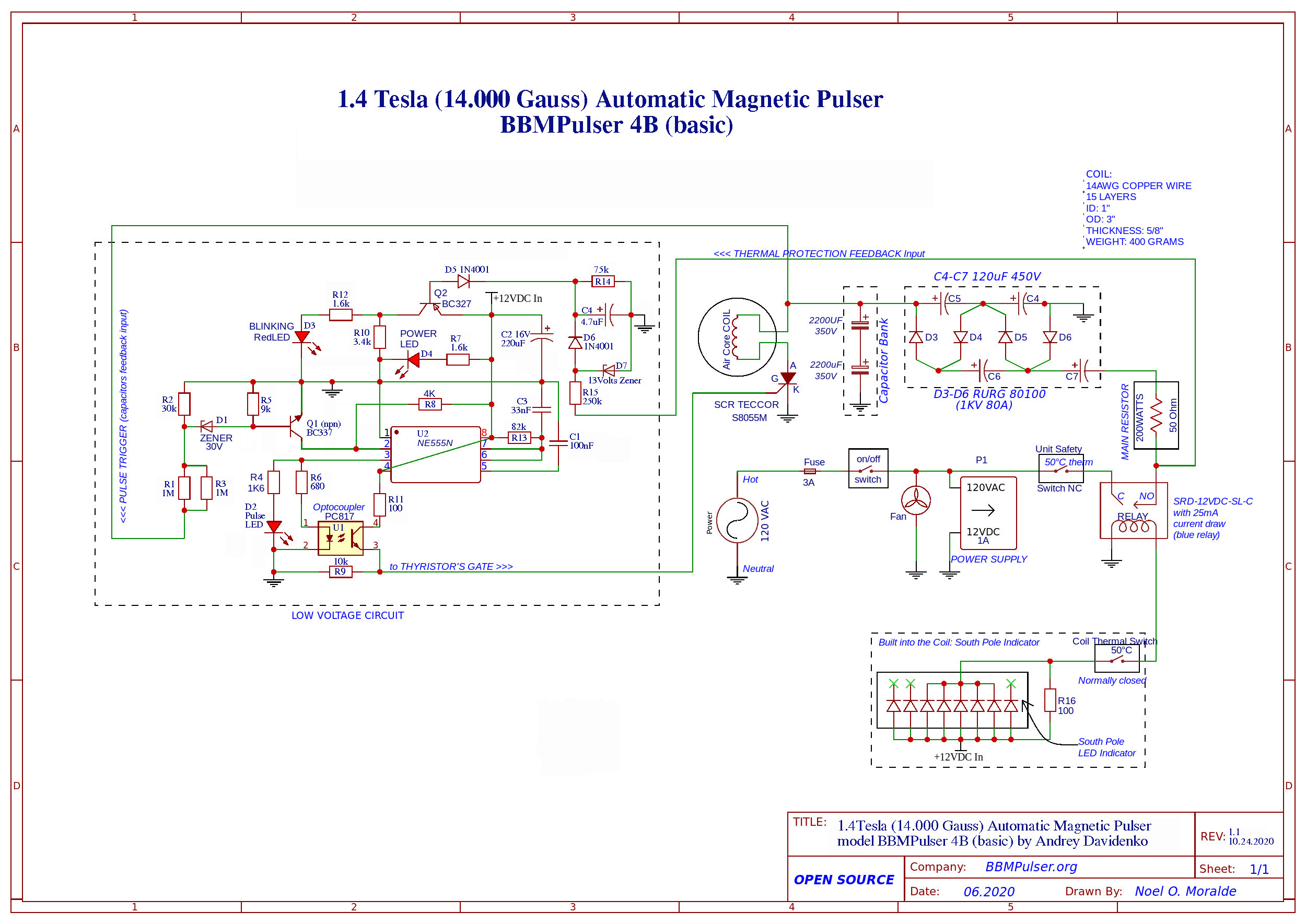
1.4 Tesla (14,000 Gauss) Automatic Magnetic Pulser BBMPulser 4B (basic) 05.2020 model
Note: this file needs to be modify.
Download your PDF file here
120 VAC Circuit

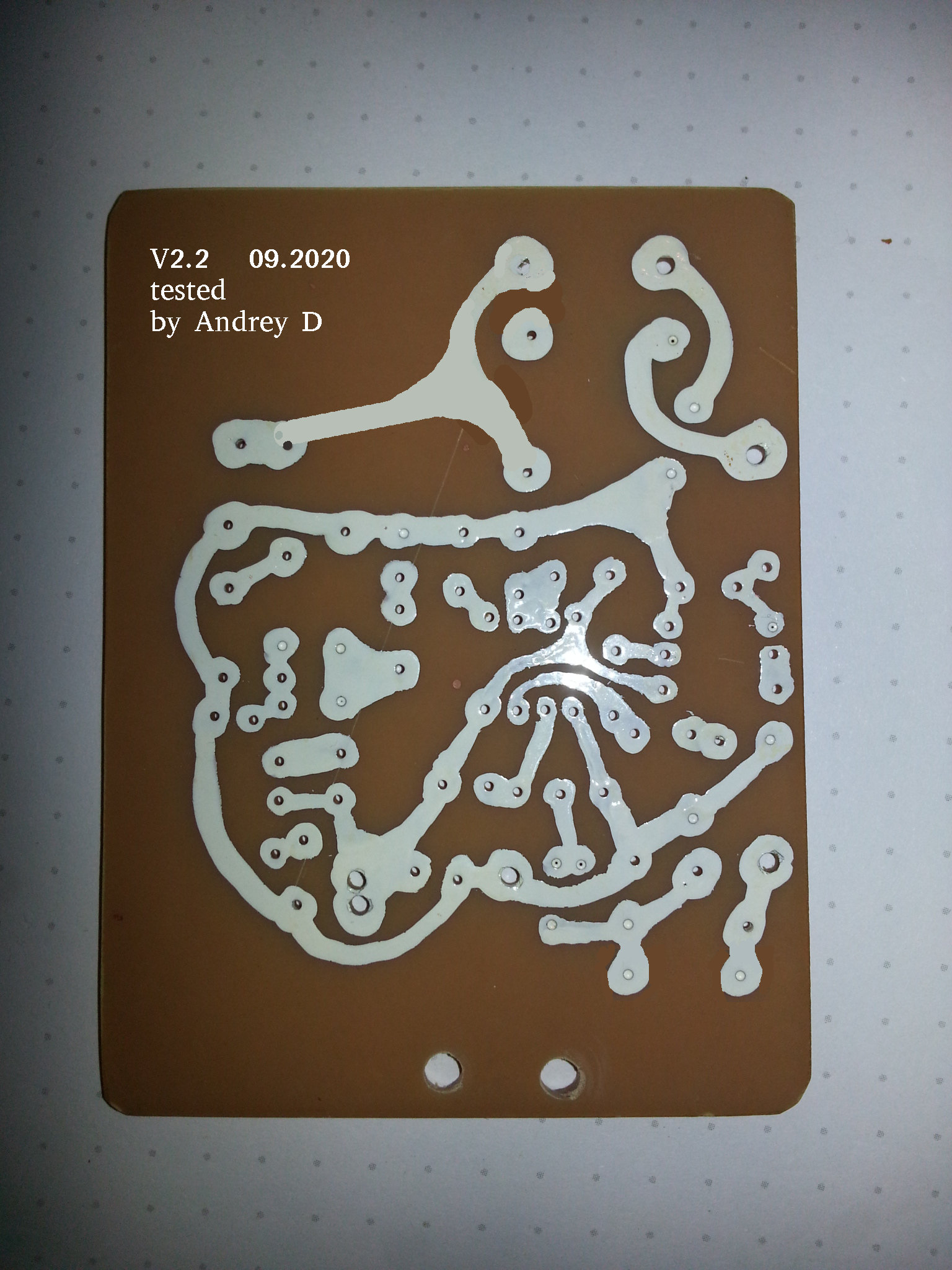
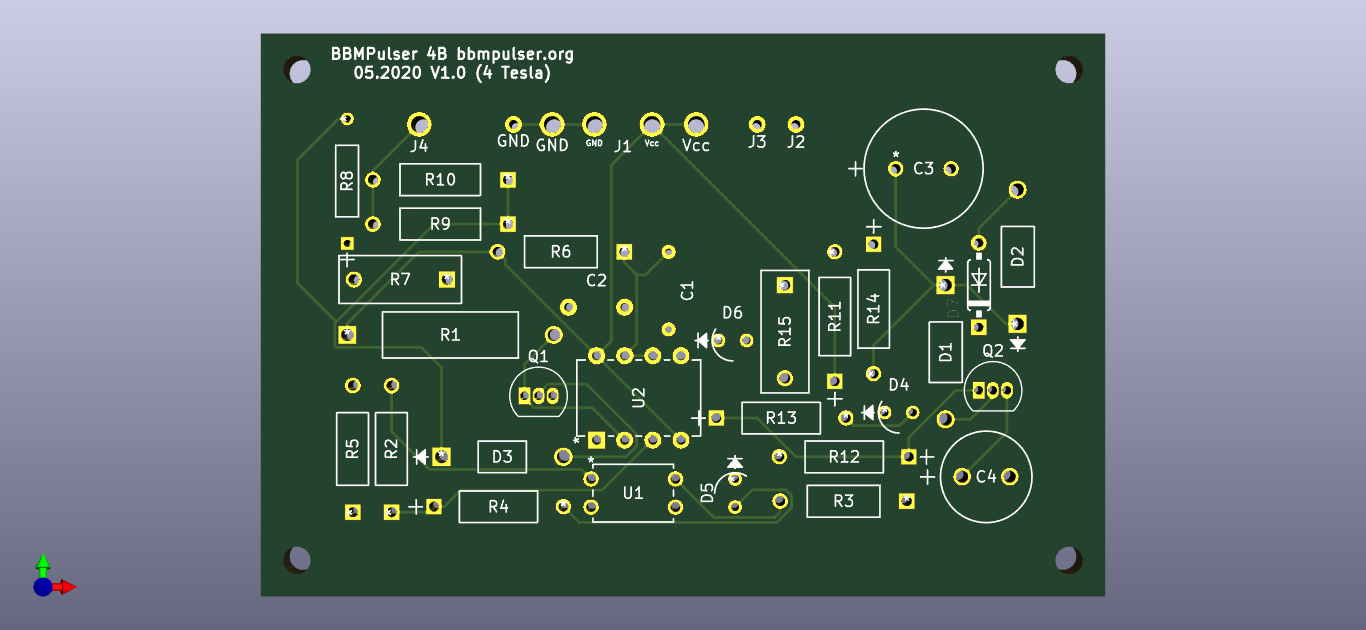
First Version of the PCB
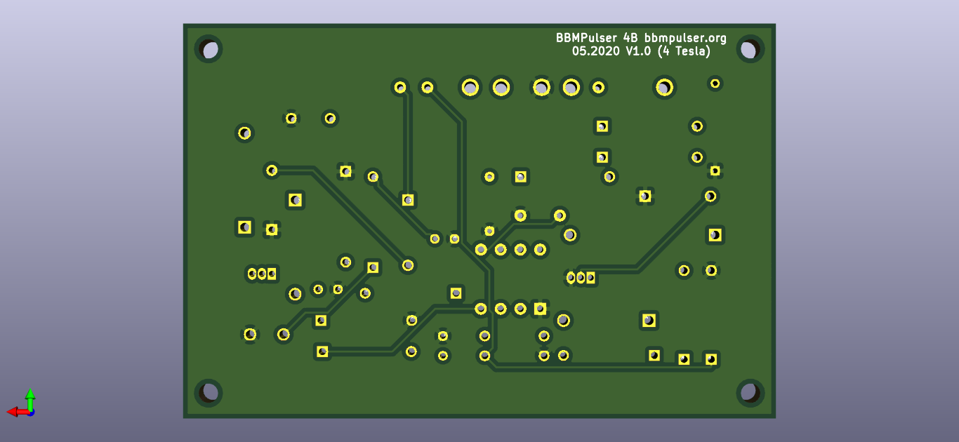
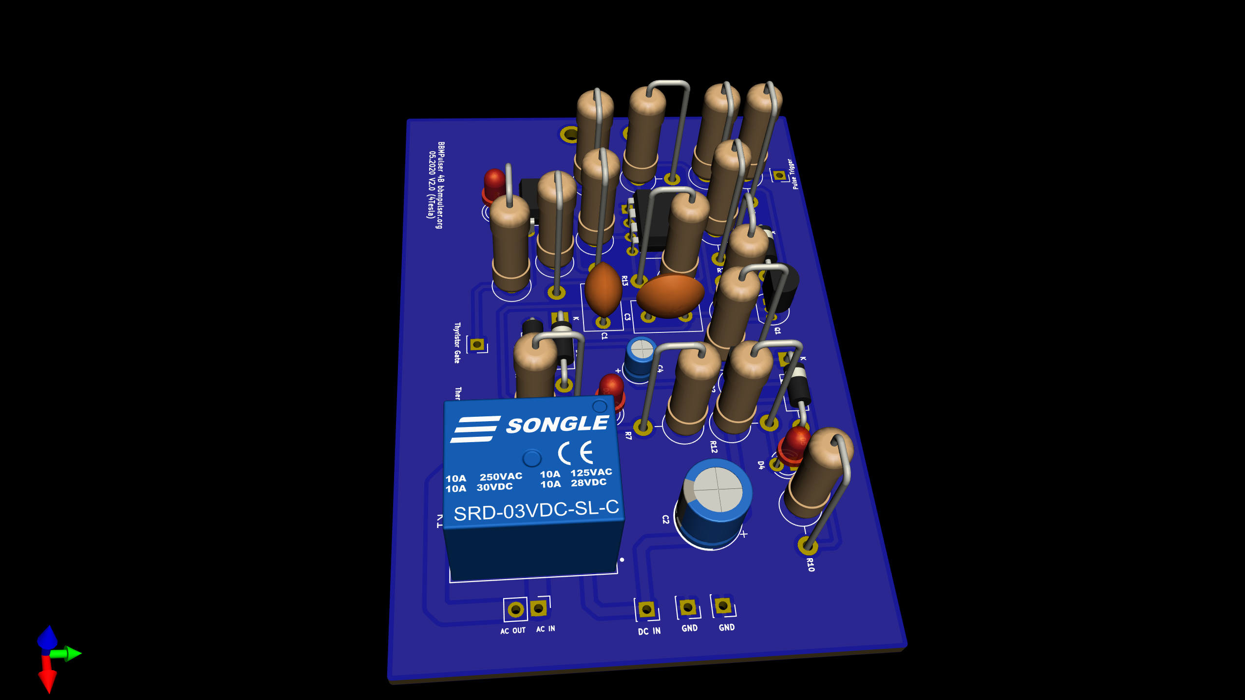
Second Version of the PCB

Thank you for viewing my circuit, BBMPulser is an Open Source Project, I started it while back around 2010 when I discovered what magnetic Pulsers are from Dr. Bob Beck Protocol titled “Take Back Your Power” here is the link to download it
This file needs to be updated.
link here: https://bbmpulser.org/wp-content/uploads/2019/12/document.pdf
That’s when I decided to build my first Unit, time has passed, since then I have built 4 models of Magnetic Pulsers with a few variations of it. The 4th model B is the Open Source Basic model, the simplest one. What you see is the latest circuit of the Automatic Magnetic Pulser capable of delivering 4+ Tesla (40,000 Gauss) Magnetic Pulse at the surface of the coil. If put together correctly and proper values components are used – this circuit should work for years! It’s been tested and proven to be reliable. Please read all the precautions and the notes, I know your time is very valuable but the circuit has HIGH VOLTAGE 650 Volts, there is a RISK of getting shocked or being injure if not handled correctly.
Please note just like any other High Voltage circuit, this circuit can be Dangerous due to the High Voltage and fairly LARGE Capacitor Bank. Please Use large (100-300 Watts 50 Ohms resistor) to discharge the capacitors every time, before working or testing the circuit. Please be very careful and DO NOT SHORT charged Capacitors. Please DO NOT DO IT, its very Dangerous!. Myself or the Graphic Designer Can NOT be held responsible for anything occurring from miss-wiring or mishandling this circuit or from using this circuit incorrectly. You are taking full responsibility working with this circuit. With that being said, lets get to it:
Please Use set values components, fail to use proper components may result in circuit malfunctioning and possibly failure.
Kits are available for this circuit. Kit will have everything you will need to build 1 complete Unit. I suggest you look into this option for couple of reasons
a) all pre-made and ready to go, you will build it to the specs
b) save time, one purchase is all you need, no need to look for component all over the internet
c) with the kit you will get the handle all molded, case all drilled, modules pre-assembled, + do-it yourself Video how to put the kit together. This will save your time.
Do-it yourself Kit for 40,000 Gauss Automatic Magnetic Pulser model BBMPulser 4B available at bbmpulser.org/kits or click here
The circuit is designed to operate in Automatic mode, futures double Thermal safety protection with a visual alarm, (blinking red LED) and South Pole LED indicator molded into the core on the south side of the coil. I tried to use the least amount of components to get desired results while designing this circuit, the way I see it is the simplicity = reliability. The circuit consist of high and low voltage sides. There is a part of the circuit labeled Low Voltage, works off 12VDC build in power supply and other part is a high voltage side consists of Capacitor Bank, Capacitor charging circuit, Thyristor and main 50 Ohms 200 Watts Resistor. This side can have up to 600 Volts.
The main 200 Watts Resistor could be made of 30 AWG Nickel Chromium Resistance wire, you will need ~7ft to have 50 Ohms, wrap it spaced around a peace of ceramic tile, add some supporting brackets on the sides for mounting and you done. Please see the picture of the examples for the main resistor I built.
The 4 Diodes from the capacitor charging circuit and the Thyristor, needs to be insulated and placed on aluminum Heat sink, You only need 1″x4″x1/2″ heat sink block for all 5 components. You must insulate using materials like mica sheets between the back of the diodes, Thyristor and aluminum heat sink. Please use proper none conductive thermal compound, do NOT use one with the silver in it as its conductive.
Wires between coil and the unit.
Use 2x12AWG multi stranded (64 strands) copper wires 6ft long to connect between coil and the Unit. Use 2x18AWG wires to connect South pole indicator with the thermal switch to the Unit. You will have total of 4 wires going to the coil, 2 thick wires and 2 thin wire. 2 thick wires are for the coil, and 2 thin wires for LED Indicator and thermal switch. I recommend sourcing the wire from the new extension cords. go to the hardware store, make sure the Extension wire is soft, bend it, then get the correct Gauge of the wire, cut it open it and use it for Pulser. I found this to be the cheapest option if you only need 12 ft of wire.
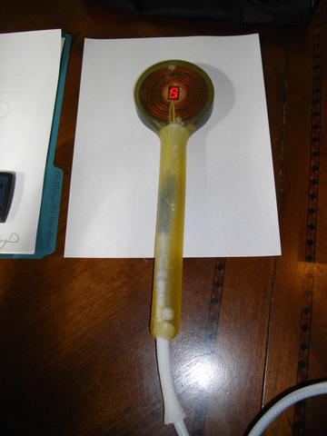
Coil. Must be tight between layers and winding. As tight as possible, no space anywhere for the wire to move. I recommend to put tape over each layer insulating between the layers when winding the coil. What’s important is the wire Gauge and the total length of the wire. For the circuit presented the coil must be made of 14AWG copper magnet wire totaling ~395-400 gram. Minimum weight of the coil is 350 gram, smaller coil will put more load on the circuit and will result in Thyristor failure.
The fan is 120VAC, 4″ brush less fan low to medium air flow. Its needed to remove excess heat from the main resistor and some components.
Thermal Switches both 50C auto-recoverable. Both Normally Closed. When triggered by heat they will open the line. Both are used in Thermal Protection circuit as a Safety future. One installed inside the unit, second installed on the side of the coil to sense the coil temperature and trigger when temperature gets too hot
The 555 Chip is the heart of the Pulser. Its configured to run in Mono-stable mode, it requires a trigger in order to put out 3 millisecond pulse (pin3) it gets its trigger from the triggering circuit consist of Q1 NPN Transistor, 30 Volt Zenner Diode and a few resistors that’s actively measuring Capacitor bank voltage and waits for it to raise to ~ 550 Volts before sending a trigger signal to the Chip. The chip will take the signal and make 3 ms pulse from it sending it to the optocoupler.
Optocoupler is used to insulate between low and high voltage and to boost control current to the Thyristors Gate. When Thyristor gets 3ms control signal it will act as a relay and will connect capacitor bank to the coil for 3ms. This will result in intense magnetic spike from the coil and it will discharge the capacitor Bank from 550Volts to around 60 Volts. Since capacitors are connected to the charging circuit they will start charging, it takes around 5 seconds to recharge them back to 550Volts after which the cycle repeats making monostable circuit to work in Astable mode. (Auto-trigger based off voltage)
The other part of the low Voltage Circuit is the “Protec” circuit. Here is how it works. This circuit actively seeks for 120VAC phase after 2 thermal switches, if 120VAC hot wire (phase) is lost it will trigger by activating red blinking LED. (Visual Alarm)
The Red Blinking LED, its a special LED that has micro circuit build into it which make LED Blink when Power applied instead of continues light as any other LEDs would.
When buying this LED – make sure its marked as “blinking LED”. You can substitute it with the regular red LED, it will not be blinking when activated.
The 120VAC to 12VDC Power supply, please use between 500ma to 2 Amp power supply. Ideal is 1 Amp 12 Volt.
Pulse LED – Blue, Power LED Green, Protec LED – Blinking Red.
Please Note. The ground of the circuit is not your chassis ground. Chassis Ground gets connected only to the metal case of the unit, it does not connects to the circuit ground. This 2 grounds are not connected together. They are different. So remember the ground wire from the outlet connects only to the metal case of the unit grounding it. It does NOT connects to the internal circuit ground. If you are using plastic casing then you don’t need to bring ground wire to the unit, all you need is the Hot and the Neutral.
If you have a suggestions on improving or adding additional futures to the circuit you can eMail me your Ideas to: ideas@bbmpulser.org I will look into them and if I find it Useful I will add your idea to the next version of the Magnetic Pulsers circuits.
Please note, You cannot commercially manufacture this circuit, If you need Printed Circuit Board PCB with all the components – please go to the www.bbmpulser.org/kits where you will find all you need to build a complete 4 Tesla Unit.
The kits will be ready soon, please check back for availability.
Thank You Noel M. for taking your time and drawing this circuit for us on the Computer. You have done an outstanding work, We are all appreciate it and thanking you for it.!
BBMPulser is an Open Source Project, Your support is greatly appreciated and helps me move forward designing even better circuits with more unique futures. Thank You for Your support.
Please check out my YouTube channel I will be posting how to build the Unit from Do-it yourself kit, also I have many Videos performing true repel tests with heavy aluminum weights demonstrating power output from the Units using similar circuits.
I have couple more circuits for model S and model D, this circuits are not open source yet. I will consider exposing the circuit to those models if I get enough interest and involvement with the current circuit for model B (basic)
I wish you success building this Unit and Using it. I thank you for taking your time and looking into it and your support and feedback.
Please share this circuit with your friend and anyone who needs it.
Save it on your computer, If you don’t need it now – you may need it later, its free.
Andrey D
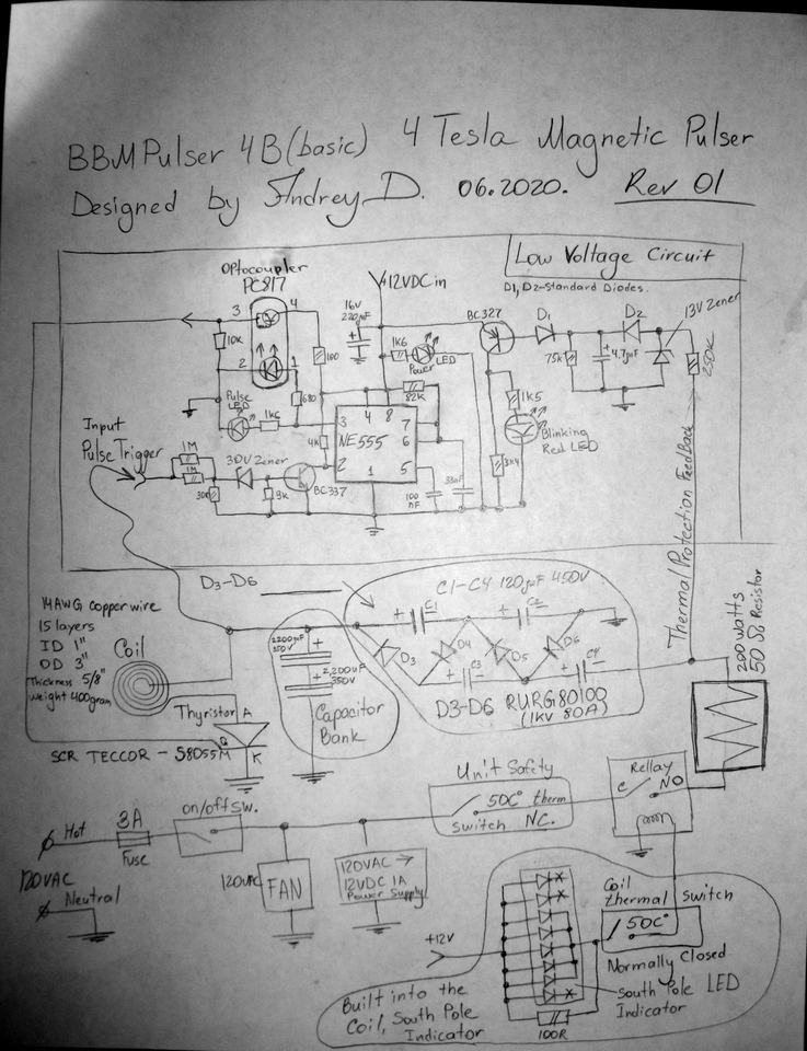
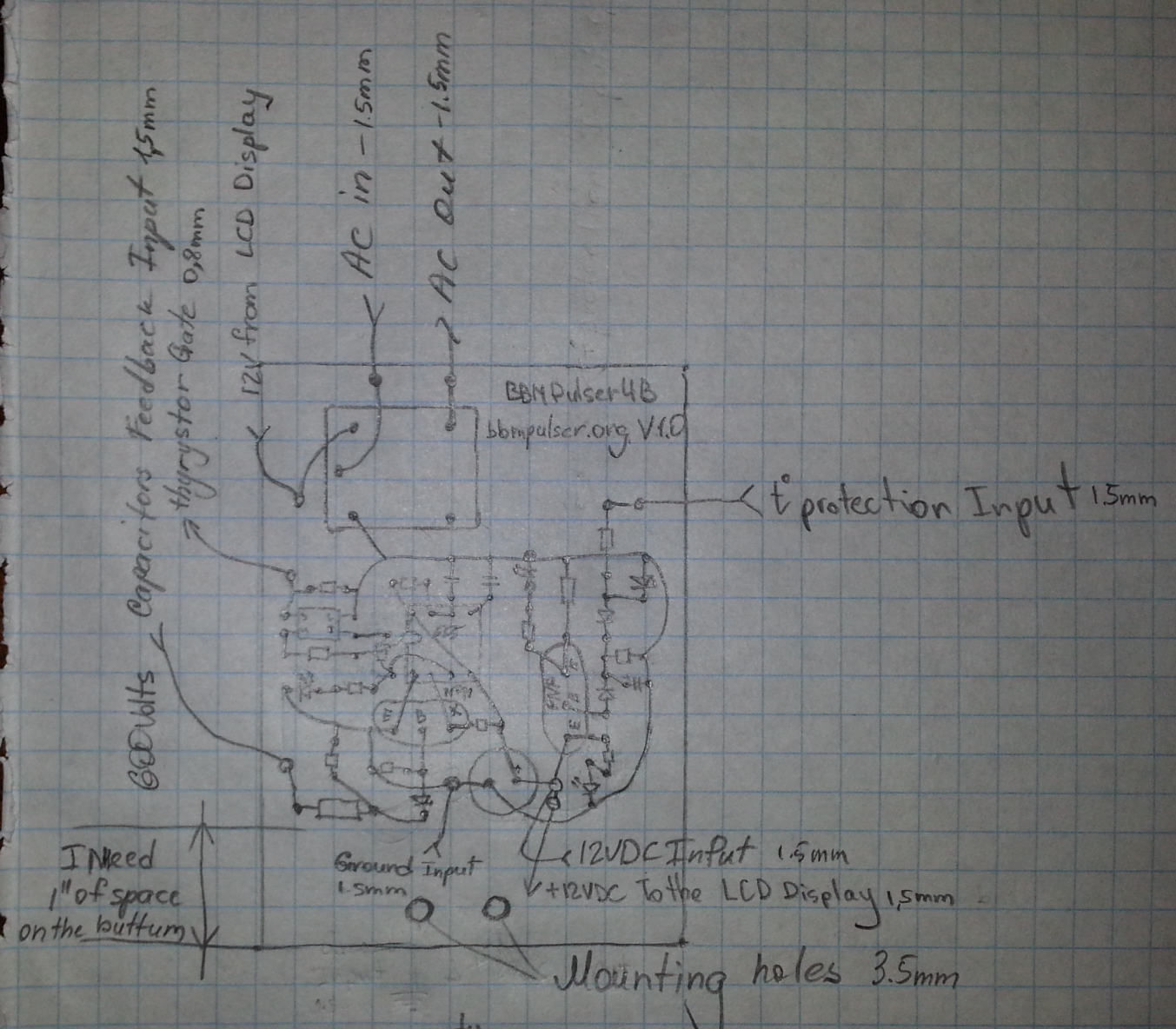
Here is the original circuit I drew by hand, it does have one small error (Thermal Protection Feedback needs to be connected to the other side of 200 Watts Resistor) . Please use the modified circuits above. Use this circuit as a reference
My original layout of the components for BBMPulser 4B model 07/2020
This is hand made version of the PCB BBMPulser 4B